I bought a set of 3 eero Pro 6 mesh (Wi-Fi 6) routers back at the end of 2023, and the first one of them died in the last few weeks. Trying to power the device via USBC no longer does anything, and eero support didn’t have much to try other than the reset button and a new power adapter. So I figured I would take it apart and have a look inside just incase it was something super obvious (it was not). So here is a little overview of what’s inside an Eero Pro 6, and how to get in!
Teardown
Before starting, I found this Reddit post which shown an image of a screw on a different eero device, hidden under the label, and that was the same on the eero Pro 6, except the label revealed 2 screws.
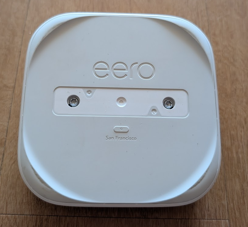
These were 2x size 20 torx bits, and were very easy to undo, and with a little prying around the edge with a plastic pry tool, I managed to pop the bottom plate off.
This bottom plate revealed the real button, but also 4 black plastic clips, and 4 more torx screws, this time size 15.
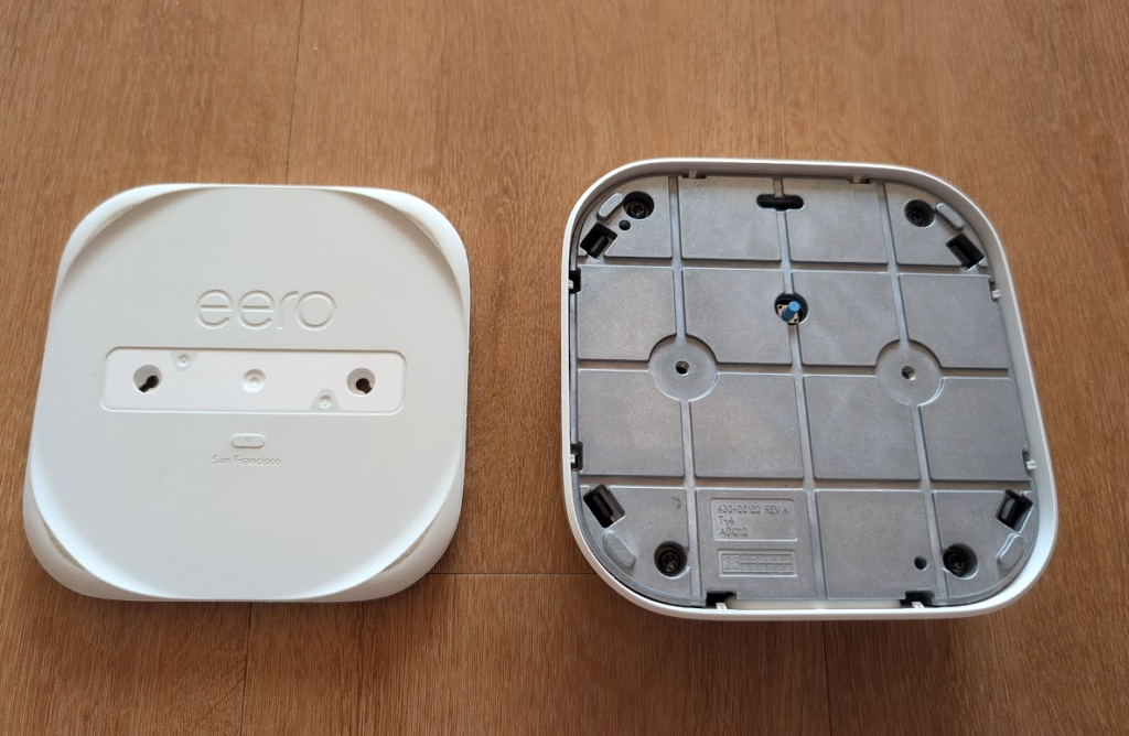
Taking these next 4 size 15 torx screws out then allows you to pop the top off the device, revealing a PCB with a chunky heatsink, and a plastic frame that seems to carry most of the devices antennas.
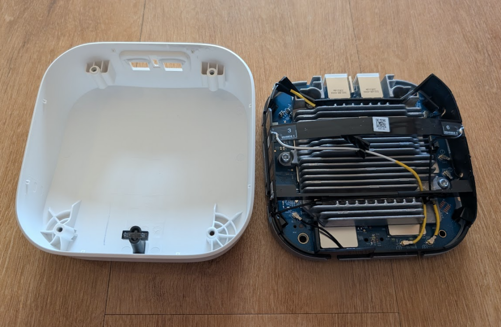
This plastic frame can then be removed by unclipping the black plastic clips using a pry tool or small screw driver.
Each of the antenna connectors then needs to be disconnected, and you might benefit from some long nose pliers for this step.

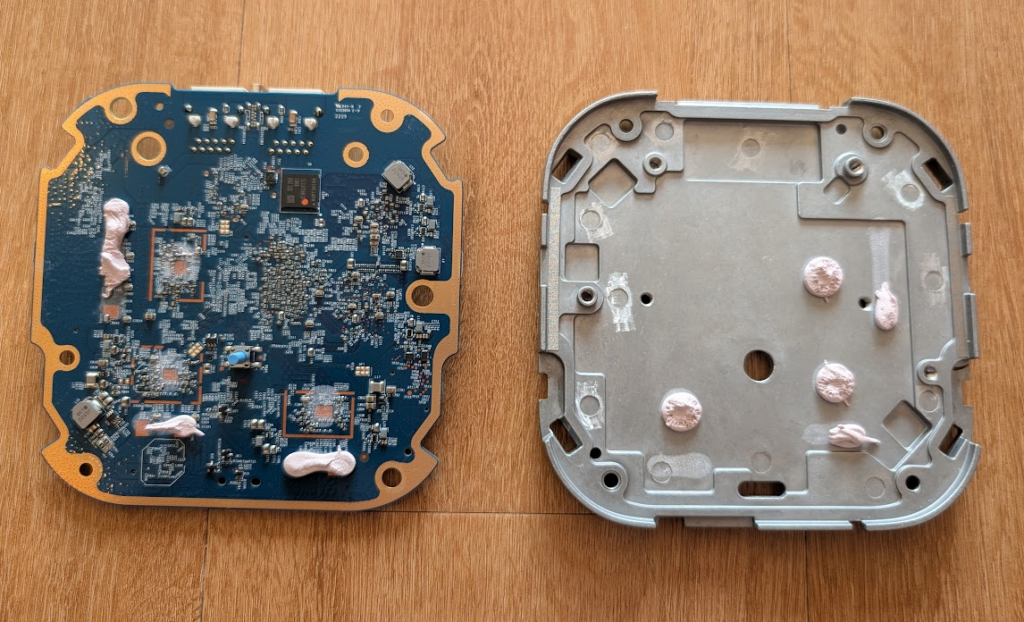
With the plastic frame off, there are 4 more torx screws (also size 15) that need to be undone to take the main heatsink off, it should pull of easily after that, mine only add a small blob of thermal gloop.
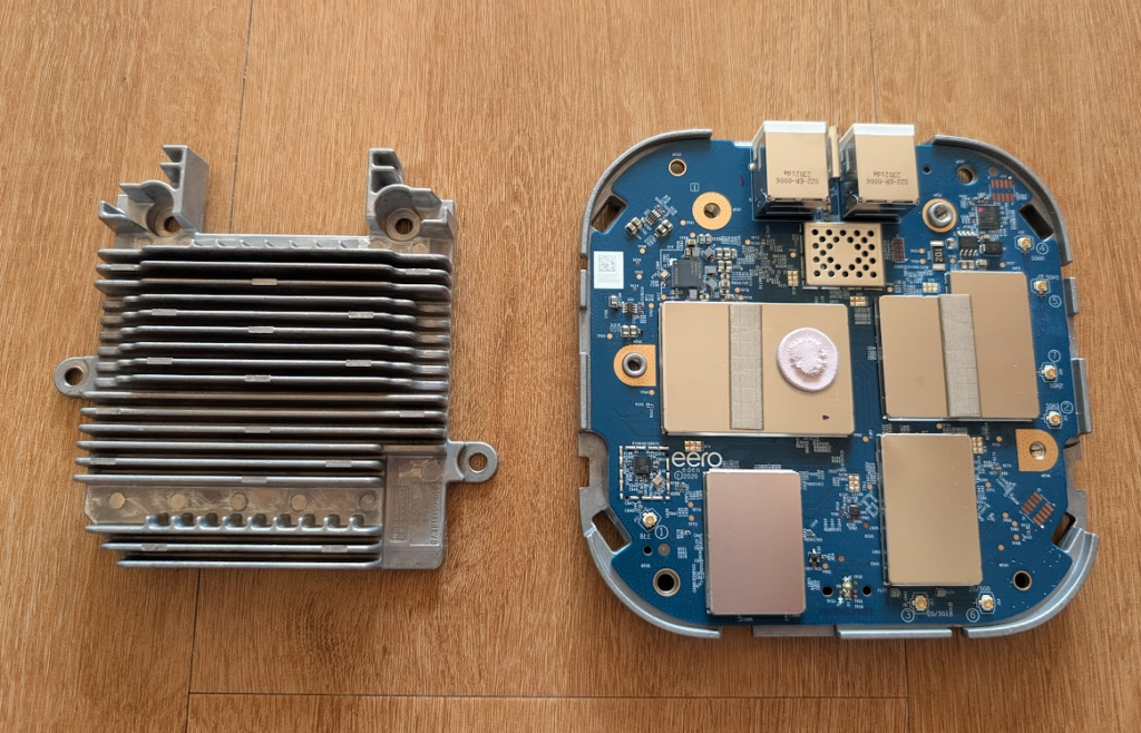
At this stage, the PCB is also easy to lift out / off from the metal backing plate, as there is just a little bit more thermal gloop connecting the two.
Components
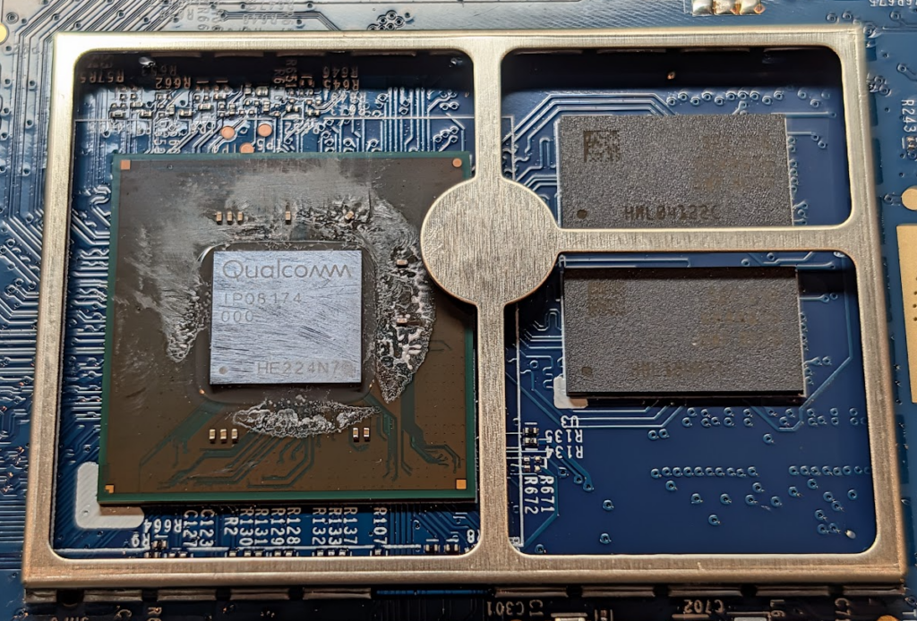
Looking under the main shield, there is a Qualcomm IPQ8174 SoC, part of their Networking Pro 800 Platform. It’s a 64 bit quad core ARM Cortex CPU.
Next to it are some Samsung DDR4 SDRAM (K4A4G165WF-BCTD) which are 4Gb (Gigabit) each (I believe) and thus a total of 1GB RAM for the system.
There are then 2 different shapes of shield left, starting with the largest…
A Wi-Fi Radio Front-End in the form of a Qualcomm QCN5054, which is a a dedicated 802.11ax (Wi-Fi 6) radio chip, along with a number of FEMs, DM69 / FLT (Filters).
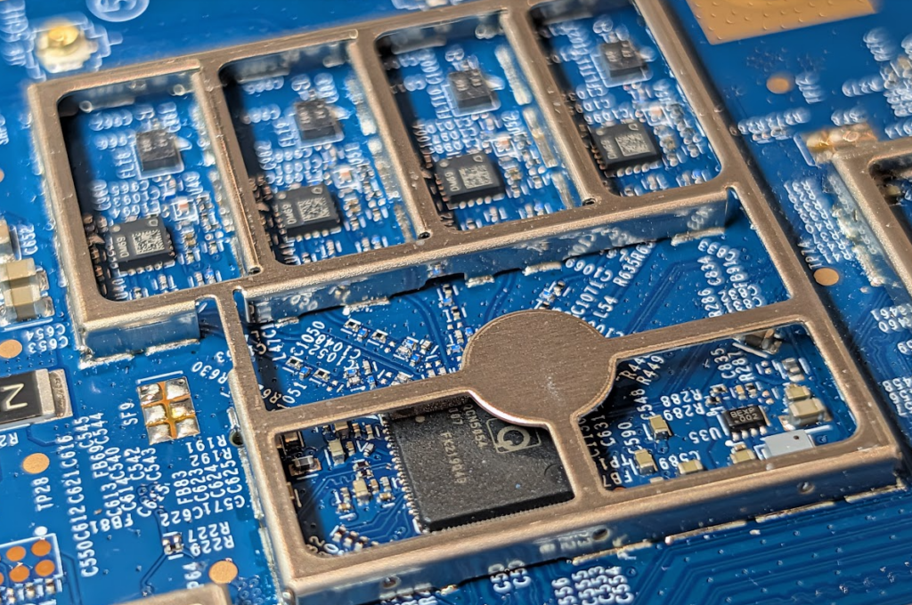
One of the other 2 shields has a QCN5024. and the other a 5054. The QCN5054 is typically used for the 5GHz band, while the QCN5024 is typically used for 2.4GHz.
The other shielded areas seem to include the same DM69s and filters as the largest.

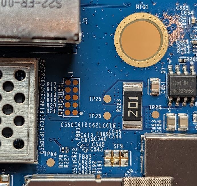
Somewhere near the the USBC power, there appears to be a 5 by 2 pins, that looks like a 10-pin ARM JTAG interface, similar to what has also been seen in a eero 6 (3rd gen 2020).
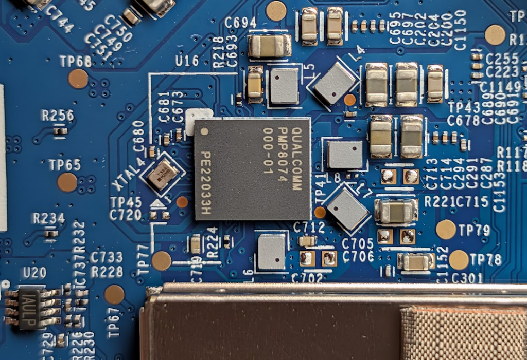
And then the other larger components all seemed to be power and USBC related, with a Cypress (now Infineon) EZ-PD™ CCG3 USB C Port Controller, and a Qualcomm PMP8074 Power Management circuit.


Repair? or?
I probably don’t want to repair this myself, an nothing jumped out when looking around in term of short, or things that were not as they should be.
Looking on Ebay, it looks like you can actually pick one of these up second hand for £40 delivery included.
Eero did give me a $50 out-of-warranty discount code as the product died outside of warranty for seemingly no reason, and looking at their shop, the equivalent replacement would get me WiFi 7 at the base price of £169, which after the discount would be around £132.54. In April the base price on Amazon was actually £120, and even in May it was £135, so maybe I won’t jump in and buy one now, though I can could image the price might keeping going up given the state of the world.
But also, given my network still has 2 Eeros in it, and I can still easily reach ~450 Mbps in the room that this last router was located, perhaps I didn’t need 3 after all.